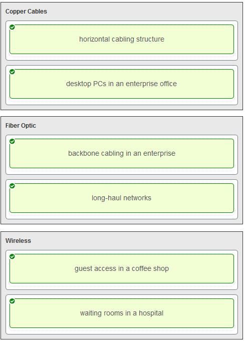
- the amount of traffic that is currently crossing the network
- the type of traffic that is crossing the network
- the latency that is created by the number of network devices that the data is crossing
- the sophistication of the encapsulation method applied to the data
- the bandwidth of the WAN connection to the Internet
- the reliability of the gigabit Ethernet infrastructure of the backbone
- It is not affected by EMI or RFI.
- It is more expensive than UTP cabling is.
- Each pair of cables is wrapped in metallic foil.
- It combines the technique of cancellation, shielding, and twisting to protect data.
- It typically contains 4 pairs of fiber-optic wires.
- create the signals that represent the bits in each frame on to the media
- provide physical addressing to the devices
- determine the path packets take through the network
- control data access to the media
- the magnetic field around the adjacent pairs of wire
- the use of braided wire to shield the adjacent wire pairs
- the reflection of the electrical wave back from the far end of the cable
- the collision caused by two nodes trying to use the media simultaneously
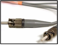
- fiber
- STP
- UTP
- coax
- crosstalk
- electromagnetic interference
- bandwidth
- size of the network
- signal modulation technique
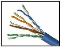
- UTP
- STP
- coax
- fiber
- cordless phones
- microwaves
- Blu-ray players
- home theaters
- incandescent light bulbs
- external hard drives
- It manages the access of frames to the network media.
- It packages various Layer 3 PDUs into a frame format that is compatible with the network interface.
- It defines the end-to-end delivery addressing scheme.
- It maintains the path between the source and destination devices during the data transmission.
- It provides reliable delivery through link establishment and flow control.
- It ensures that application data will be transmitted according to the prioritization.
- to verify the integrity of the received frame
- to verify the physical address in the frame
- to verify the logical address in the frame
- to compute the checksum header for the data field in the frame
- error detection
- data
- physical address
- logical address
- They vary depending on protocols.
- They all include the flow control and logical connection fields.
- Ethernet frame header fields contain Layer 3 source and destination addresses.
- They include information on user applications.
- partial mesh
- mesh
- hub and spoke
- point-to-point
- Frame Check Sequence
- minimum frame size
- auto-MDIX
- CEF
- source MAC address
- full-duplex
- deterministic
- half-duplex
- controlled access
- End devices connect to a central intermediate device, which in turn connects to other central intermediate devices.
- End devices are connected together by a bus and each bus connects to a central intermediate device.
- Each end system is connected to its respective neighbor via an intermediate device.
- All end and intermediate devices are connected in a chain to each other.
- It places information in the frame allowing multiple Layer 3 protocols to use the same network interface and media.
- It provides the logical addressing required that identifies the device.
- It provides delimitation of data according to the physical signaling requirements of the medium.
- It defines software processes that provide services to the physical layer.
- Ethernet utilizes CSMA/CD.
- Media access control provides placement of data frames onto the media.
- Data link layer protocols define the rules for access to different media.
- Contention-based access is also known as deterministic.
- 802.11 utilizes CSMA/CD.
- Networks with controlled access have reduced performance due to data collisions.
- The physical address is added.
- An IP address is added.
- The logical address is added.
- The process port number is added.
- source MAC address
- destination MAC address
- error-checking information
- source IP address
- destination IP address
- access method
- flow control
- message encapsulation
- message encoding
- header
- data
- trailer
- type field
- MTU size
- CRC value
- All network devices must listen before transmitting.
- When a device hears a carrier signal and transmits, a collision cannot occur.
- A jamming signal causes only devices that caused the collision to execute a backoff algorithm.
- Devices involved in a collision get priority to transmit after the backoff period.
- the automatic configuration of an interface for a straight-through or a crossover Ethernet cable connection
- the automatic configuration of an interface for 10/100/1000 Mb/s operation
- the automatic configuration of full-duplex operation over a single Ethernet copper or optical cable
- the ability to turn a switch interface on or off accordingly if an active connection is detected
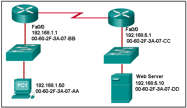
- 00-60-2F-3A-07-CC
- 00-60-2F-3A-07-AA
- 00-60-2F-3A-07-BB
- 00-60-2F-3A-07-DD
- shared memory buffering
- port-based buffering
- level 1 cache buffering
- fixed configuration buffering
- fast-forward switching
- fragment-free switching
- store-and-forward switching
- CRC switching
- QOS switching
- store-and-forward switching
- cut-through switching
- fragment-free switching
- fast-forward switching
- to determine if errors occurred in the transmission and reception
- to obtain the MAC address of the sending node
- to verify the logical address of the sending node
- to compute the CRC header for the data field
- fast-forward
- cut-through
- store-and-forward
- fragment-free
- The link between the switches will work at the fastest speed that is supported by both switches.
- The link between switches will work as full-duplex.
- The auto-MDIX feature will configure the interfaces eliminating the need for a crossover cable.
- If both switches support different speeds, they will each work at their own fastest speed.
- The connection will not be possible unless the administrator changes the cable to a crossover cable.
- The duplex capability has to be manually configured because it cannot be negotiated.
- frame error checking
- collision detecting
- faster frame forwarding
- frame forwarding using IPv4 Layer 3 and 4 information
- CRC in the trailer
- source MAC address in the header
- destination MAC address in the header
- protocol type in the header
- store-and-forward
- cut-through
- fast-forward
- fragment-free
- using the source MAC addresses of frames to build and maintain a MAC address table
- utilizing the MAC address table to forward frames via the destination MAC address
- building a routing table that is based on the first IP address in the frame header
- forwarding frames with unknown destination IP addresses to the default gateway
- examining the destination MAC address to add new entries to the MAC address table
- Logical link control is implemented in software.
- The data link layer uses LLC to communicate with the upper layers of the protocol suite.
- Logical link control is specified in the IEEE 802.3 standard.
- The LLC sublayer adds a header and a trailer to the data.
- The LLC sublayer is responsible for the placement and retrieval of frames on and off the media.
- It enables a device to automatically configure an interface to use a straight-through or a crossover cable.
- It enables a device to automatically configure the duplex settings of a segment.
- It enables a device to automatically configure the speed of its interface.
- It enables a switch to dynamically select the forwarding method.
- has a lower latency appropriate for high-performance computing applications?
- has a positive impact on bandwidth by dropping most of the invalid frames
- makes a fast forwarding decision based on the source MAC address of the frame
- provides the flexibility to support any mix of Ethernet speeds
- 01-00-5E-00-00-03
- FF-FF-FF-FF-FF-FF
- 5C-26-0A-4B-19-3E
- 00-26-0F-4B-00-3E
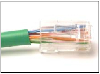
- The untwisted length of each wire is too long.
- The woven copper braid should not have been removed.
- The wrong type of connector is being used.
- The wires are too thick for the connector that is used.

- 1 – rollover, 2 – straight-through, 3 – crossover
- 1 – rollover, 2 – crossover, 3 – straight-through
- 1 – crossover, 2 – straight-through, 3 – rollover
- 1 – crossover, 2 – rollover, 3 – straight-through
Which port does Switch0 use to send frames to the host with the IPv4 address 10.1.1.5?
- Fa0/11
- Fa0/1
- Fa0/5
- Fa0/9
- loss of signal strength as distance increases
- time for a signal to reach its destination
- leakage of signals from one cable pair to another
- strengthening of a signal by a networking device
- greater distances per cable run
- limited susceptibility to EMI/RFI
- greater bandwidth potential
- lower installation cost
- durable connections
- easily terminated
- modulation
- IEEE
- EIA/TIA
- air
- bandwidth
- IEEE
- EIA/TIA
- air
- bandwidth
- goodput
- throughput
- latency
- throughput
- bandwidth
- latency
- goodput
- latency
- bandwidth
- throughput
- goodput
- latency
- fiber-optic cable
- air
- copper cable
- goodput
- fiber-optic cable
- air
- copper cable
- copper cable
- fiber-optic cable
- air
- goodput
- fiber-optic cable
- goodput
- latency
- throughput
- air
- goodput
- latency
- throughput
- Implements a trailer to detect transmission errors.
- Controls the NIC responsible for sending and receiving data on the physical medium.
- Places information in the frame that identifies which network layer protocol is being used for the frame.
- Adds Layer 2 control information to network protocol data.
- Enables IPv4 and IPv6 to utilize the same network interface and media.
- Enables IPv4 and IPv6 to utilize the same network interface and media.
- Places information in the frame that identifies which network layer protocol is being used for the frame.
- Integrates various physical technologies.
- Implements a process to delimit fields within a Layer 2 frame.
- Controls the NIC responsible for sending and receiving data on the physical medium.
- Provides a mechanism to allow multiple devices to communicate over a shared medium.
- Controls the NIC responsible for sending and receiving data on the physical medium.
- Places information in the frame that identifies which network layer protocol is being used for the frame.
- Adds Layer 2 control information to network protocol data.
- Communicates between the networking software at the upper layers and the device hardware at the lower layers.
- Controls the NIC responsible for sending and receiving data on the physical medium.
- Integrates various physical technologies.
- Communicates between the networking software at the upper layers and the device hardware at the lower layers.
- Adds Layer 2 control information to network protocol data.
- Places information in the frame that identifies which network layer protocol is being used for the frame.
- Adds Layer 2 control information to network protocol data.
- Places information in the frame that identifies which network layer protocol is being used for the frame.
- Performs data encapsulation.
- Controls the NIC responsible for sending and receiving data on the physical medium.
- Integrates various physical technologies.
- Provides synchronization between source and target nodes.
- Integrates various physical technologies.
- Communicates between the networking software at the upper layers and the device hardware at the lower layers.
- Adds Layer 2 control information to network protocol data.
- Enables IPv4 and IPv6 to utilize the same network interface and media.
- Adds Layer 2 control information to network protocol data.
- Enables IPv4 and IPv6 to utilize the same network interface and media.
- Provides data link layer addressing.
- Implements a trailer to detect transmission errors.
- Provides synchronization between source and target nodes.
- Implements a trailer to detect transmission errors.
- Provides synchronization between source and target nodes.
- Places information in the frame that identifies which network layer protocol is being used for the frame.
- Enables IPv4 and IPv6 to utilize the same network interface and media.
- Adds Layer 2 control information to network protocol data.
- Enables IPv4 and IPv6 to utilize the same network interface and media.
- Adds Layer 2 control information to network protocol data.
- Integrates various physical technologies.
- Implements a trailer to detect transmission errors.
- Provides synchronization between source and target nodes.
- Provides a mechanism to allow multiple devices to communicate over a shared medium.
- Controls the NIC responsible for sending and receiving data on the physical medium.
- Places information in the frame that identifies which network layer protocol is being used for the frame.
- Adds Layer 2 control information to network protocol data.
- Enables IPv4 and IPv6 to utilize the same network interface and media.
- The switch refreshes the timer on that entry.
- The switch shares the MAC address table entry with any connected switches.
- The switch does not forward the frame.
- The switch sends the frame to a connected router because the destination MAC address is not local.
- The switch forwards it out all ports except the ingress port.
- The switch shares the MAC address table entry with any connected switches.
- The switch does not forward the frame.
- The switch sends the frame to a connected router because the destination MAC address is not local.
- The host will discard the frame.
- The host sends the frame to the switch to update the MAC address table.
- The host forwards the frame to the router.
- The host forwards the frame to all other hosts.
- The switch forwards it out all ports except the ingress port.
- The switch does not forward the frame.
- The switch sends the frame to a connected router because the destination MAC address is not local.
- The switch shares the MAC address table entry with any connected switches.
- The host will process the frame.
- The host forwards the frame to the router.
- The host sends the frame to the switch to update the MAC address table.
- The host forwards the frame to all other hosts.
- The switch refreshes the timer on that entry.
- The switch adds it to its MAC address table associated with the port number.
- The switch forwards the frame to the associated port.
- The switch sends the frame to a connected router because the destination MAC address is not local.
- The host will process the frame.
- The host returns the frame to the switch.
- The host replies to the switch with its own IP address.
- The host forwards the frame to all other hosts.
- The switch refreshes the timer on that entry.
- The switch shares the MAC address table entry with any connected switches.
- The switch does not forward the frame.
- The switch adds it to its MAC address table associated with the port number.
- The host will discard the frame.
- The host replies to the switch with its own IP address.
- The host forwards the frame to all other hosts.
- The host returns the frame to the switch.
- The switch forwards it out all ports except the ingress port.
- The switch refreshes the timer on that entry.
- The switch does not forward the frame.
- The switch sends the frame to a connected router because the destination MAC address is not local.
