Packet Tracer – VLSM Design and Implementation Practice
Objectives
- Part 1: Examine theNetwork Requirements
- Part 2: Design the VLSM Addressing Scheme
- Part 3: Assign IP Addresses to Devices and Verify Connectivity
Background
- In this activity, you are given a /24 network address to use to design a VLSM addressing scheme. Based on a set of requirements, you will assign subnets and addressing, configure devices and verify connectivity.
Instructions
Part 1: Examine the Network Requirements
Step 1: Determine the number of subnets needed.
- You will subnet the network address [[DisplayNet]]. The network has the following requirements:
- [[S1Name]] LAN will require [[HostReg1]] host IP addresses
- [[S2Name]] LAN will require [[HostReg2]] host IP addresses
- [[S3Name]] LAN will require [[HostReg3]] host IP addresses
- [[S4Name]] LAN will require [[HostReg4]] host IP addresses
How many subnets are needed in the network topology?
5
Step 2: Determine the subnet mask information for each subnet.
- Which subnet mask will accommodate the number of IP addresses required for [[S1Name]]?
How many usable host addresses will this subnet support? - Which subnet mask will accommodate the number of IP addresses required for [[S2Name]]?
How many usable host addresses will this subnet support? - Which subnet mask will accommodate the number of IP addresses required for [[S3Name]]?
How many usable host addresses will this subnet support? - Which subnet mask will accommodate the number of IP addresses required for [[S4Name]]?
How many usable host addresses will this subnet support? - Which subnet mask will accommodate the number of IP addresses required for the connection between
[[R1Name]] and [[R2Name]]?
Part 2: Design the VLSM Addressing Scheme
Step 1: Divide the [[DisplayNet]] network based on the number of hosts persubnet.
- Use the first subnet to accommodate the largest LAN.
- Use the second subnet to accommodate the second largest LAN.
- Use the third subnet to accommodate the third largestLAN.
- Use the fourth subnet to accommodate the fourth largestLAN.
- Use the fifth subnet to accommodate the connection between [[R1Name]] and [[R2Name]].
Step 2: Document the VLSM subnets.
- Complete the Subnet Table,listing the subnet descriptions (e.g. [[S1Name]] LAN), number of hosts needed, then network address for the subnet, the first usable host address, and the broadcast address. Repeat until all addresses are listed.
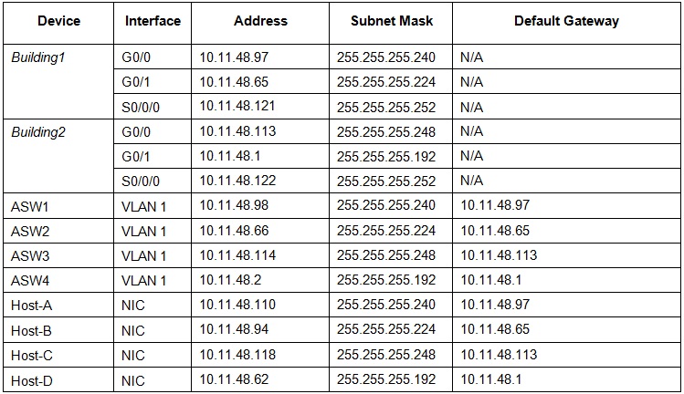
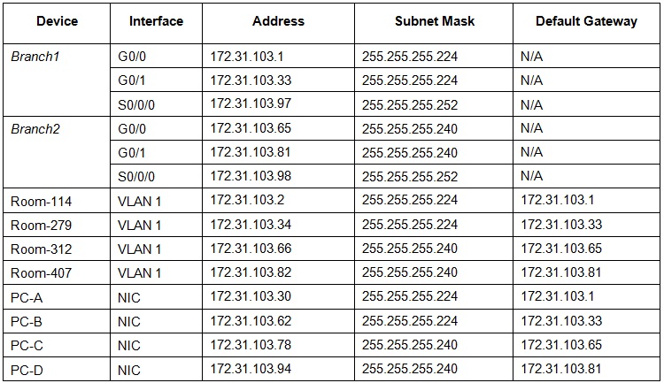
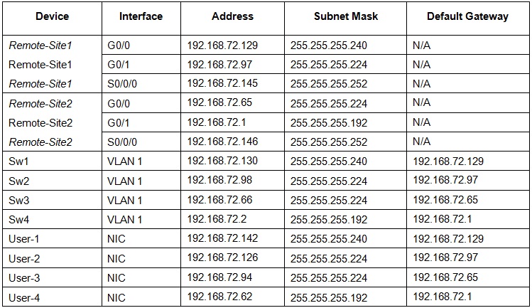
Step 3: Document the addressing scheme.
- Assign the first usable IP addresses to [[R1Name]] for the two LAN links and the WAN link.
- Assign the first usable IP addresses to [[R2Name]] for the two LAN links. Assign the last usable IP address for the WAN link.
- Assign the second usable IP addresses to the switches.
- Assign the last usable IP addresses to the hosts.
Part 3: Assign IP Addresses to Devices and Verify Connectivity
- Most of the IP addressing is already configured on this network. Implement the following steps to complete the addressing configuration.
Step 1: Configure IP addressing on the [[R1Name]] router LAN interfaces.
Step 2: Configure IP addressing on the [[S3Name]], switch including the default gateway.
Step 3: Configure IP addressing on [[PC4Name]], including the default gateway.
Step 4: Verify connectivity.
- You can only verify connectivity from [[R1Name]], [[S3Name]], and [[PC4Name]]. However, you should be able to ping every IP address listed in the Addressing Table.
Scenario 1 – Network Address: 10.11.48.0/24
Subnet Table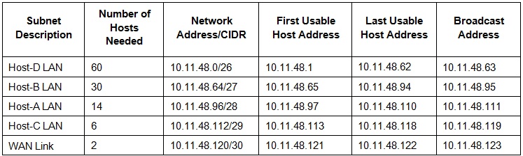
Building 1
enconf t
int g0/0
ip add 10.11.48.97 255.255.255.240
no shut
int g0/1
ip add 10.11.48.65 255.255.255.224
no shut
ASW3
enconf t
int vlan 1
ip add 10.11.48.114 255.255.255.248
no shut
ip def 10.11.48.113
Scenario 2 – Network Address: 172.31.103.0/24
Subnet Table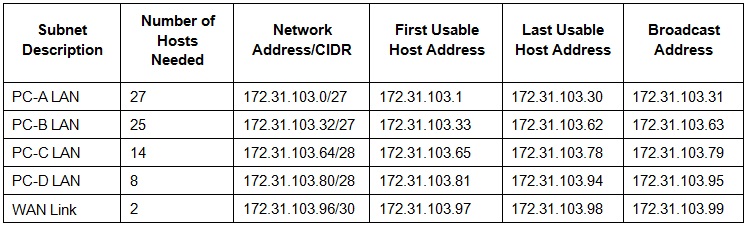
Branch 1
enconf t
int g0/0
ip add 172.31.103.1 255.255.255.224
no shut
int g0/1
ip add 172.31.103.33 255.255.255.224
no shut
Room-312
enconf t
int vlan 1
ip add 172.31.103.66 255.255.255.240
no shut
ip def 172.31.103.65
Scenario 3 – Network Address: 192.168.72.0/24
Subnet Table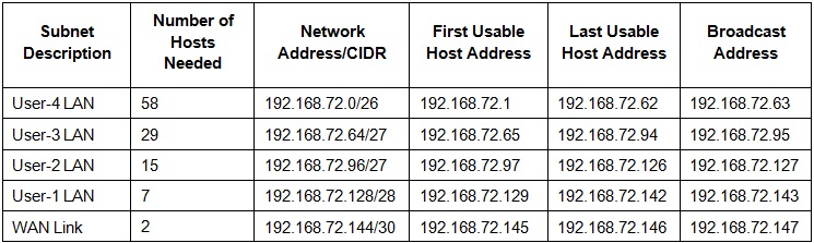
Remote-Site1
enconf t
int g0/0
ip add 192.168.72.129 255.255.255.240
no shut
int g0/1
ip add 192.168.72.97 255.255.255.224
no shut
Sw-3
enconf t
int vlan 1
ip add 192.168.72.66 255.255.255.224
no shut
ip def 192.168.72.65
