Packet Tracer – Design and Implement a VLSM Addressing Scheme
Objectives
- In this lab you will design a VLSM addressing scheme given a network address and host requirements. You will configure addressing on routers, switches, and network hosts.
- Design a VLSM IP addressing scheme given requirements.
- Configure addressing on network devices and hosts.
- Verify IP connectivity.
- Troubleshoot connectivity issues as required.
Background / Scenario
- You have been asked to design, implement, and test an addressing scheme for a customer. The customer has given you the network address that is suitable for the network, the topology, and the host requirements. You will implement and test your design.
Instructions
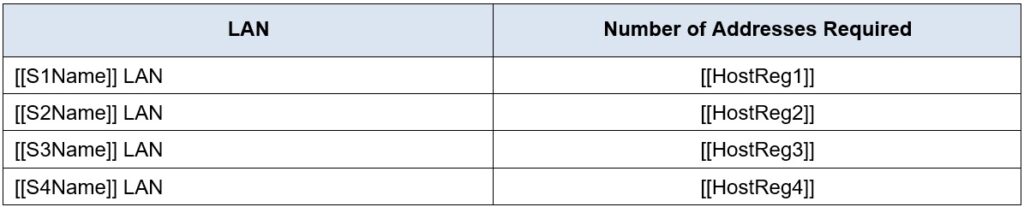
- You have been given the network address [[DisplayNet]] by your customer. The host address requirements are:
Requirements
- Host Requirements:
- Design Requirements
- Create the addressing design. Follow guidelines provided in the curriculum regarding the order of the subnets.
- The subnets should be contiguous. There should be no unused address space between subnets.
- Provide the most efficient subnet possible for the point-to-point link between the routers.
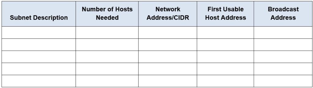
- Document your design in a table such as the one below.
- Configuration Requirements
- Note:You will configure addressing on all devices and hosts in the network.
- Assign the first usable IP addresses in the appropriate subnets to [[R1Name]] for the two LAN links and the WAN link.
- Assign the first usable IP addresses in the appropriate subnets to [[R2Name]] for the two LANs links. Assign the last usable IP address for the WAN link.
- Assign the second usable IP addresses in the appropriate subnets to the switches.
- The switch management interface should be reachable from hosts on all of the LANs.
- Assign the last usable IP addressesin the appropriate subnets to the hosts.
If the addressing design and implementation are correct, all hosts and devices should be reachable over the network.
ID:[[indexAdds]][[indexNames]][[indexTopos]]
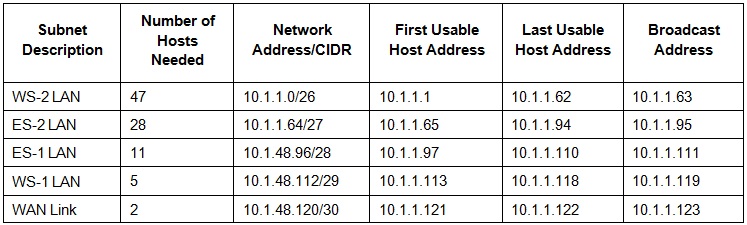
Scenario 1 – Network Address: 10.1.1.0/24
- Subnet Table
- Device Addressing Table
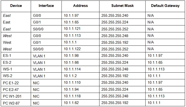
- East
- en
- conf t
- int g0/0
- ip add 10.1.1.97 255.255.255.240
- no shut
- int g0/1
- ip add 10.1.1.65 255.255.255.224
- no shut
- int s0/0/0
- ip add 10.1.1.121 255.255.255.252
- no shut
- West
- en
- conf t
- int g0/0
- ip add 10.1.1.113 255.255.255.248
- no shut
- int g0/1
- ip add 10.1.1.1 255.255.255.192
- no shut
- int s0/0/0
- ip add 10.1.1.122 255.255.255.252
- no shut
- ES-1
- en
- conf t
- int vlan 1
- ip add 10.1.1.98 255.255.255.240
- no shut
- ip def 10.1.1.97
- ES-2
- en
- conf t
- int vlan 1
- ip add 10.1.1.66 255.255.255.224
- no shut
- ip def 10.1.1.65
- WS-1
- en
- conf t
- int vlan 1
- ip add 10.1.1.114 255.255.255.248
- no shut
- ip def 10.1.1.113
- WS-2
- en
- conf t
- int vlan 1
- ip add 10.1.1.2 255.255.255.192
- no shut
- ip def 10.1.1.1
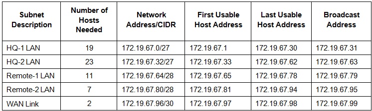
Scenario 2 – Network Address: 172.19.67.0/24
- Subnet Table
- Device Addressing Table
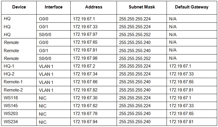
- HQ
- en
- conf t
- int g0/0
- ip add 172.19.67.1 255.255.255.224
- no shut
- int g0/1
- ip add 172.19.67.33 255.255.255.224
- no shut
- int s0/0/0
- ip add 172.19.67.97 255.255.255.252
- no shut
- Remote
- en
- conf t
- int g0/0
- ip add 172.19.67.65 255.255.255.240
- no shut
- int g0/1
- ip add 172.19.67.81 255.255.255.240
- no shut
- int s0/0/0
- ip add 172.19.67.98 255.255.255.252
- no shut
- HQ-1
- en
- conf t
- int vlan 1
- ip add 172.19.67.2 255.255.255.224
- no shut
- ip def 172.19.67.1
- HQ-2
- en
- conf t
- int vlan 1
- ip add 172.19.67.34 255.255.255.224
- no shut
- ip def 172.19.67.33
- Remote-1
- en
- conf t
- int vlan 1
- ip add 172.19.67.66 255.255.255.240
- no shut
- ip def 172.19.67.65
- Remote-2
- en
- conf t
- int vlan 1
- ip add 172.19.67.82 255.255.255.240
- no shut
- ip def 172.19.67.81
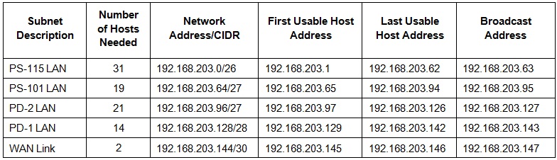
Scenario 3 – Network Address: 192.168.203.0/24
- Subnet Table
- Device Addressing Table
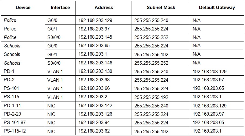
- Police
- en
- conf t
- int g0/0
- ip add 192.168.203.129 255.255.255.240
- no shut
- int g0/1
- ip add 192.168.203.97 255.255.255.224
- no shut
- int s0/0/0
- ip address 192.168.203.145 255.255.255.252
- no shut
- Schools
- en
- conf t
- int g0/0
- ip add 192.168.203.65 255.255.255.224
- no shut
- int g0/1
- ip add 192.168.203.1 255.255.255.192
- no shut
- int s0/0/0
- ip address 192.168.203.146 255.255.255.252
- no shut
- PD-1
- en
- conf t
- int vlan 1
- ip add 192.168.203.130 255.255.255.240
- no shut
- ip def 192.168.203.129
- PD-2
- en
- conf t
- int vlan 1
- ip add 192.168.203.98 255.255.255.224
- no shut
- ip def 192.168.203.97
- PS-101
- en
- conf t
- int vlan 1
- ip add 192.168.203.66 255.255.255.224
- no shut
- ip def 192.168.203.65
- PS-115
- en
- conf t
- int vlan 1
- ip add 192.168.203.2 255.255.255.192
- no shut
- ip def 192.168.203.1
